Principle of Operation and System Interface
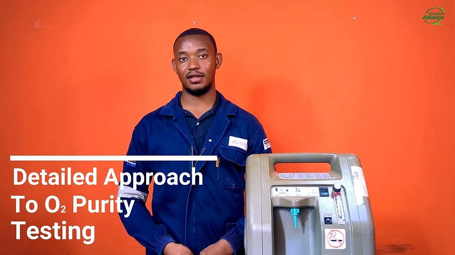
The SysMed M50 oxygen concentrator is a familiar device in hospital settings. Its core function is to generate purified oxygen using the pressure swing absorption process. A key feature for the service professional is its digital interface, which provides invaluable real-time performance data and diagnostic feedback.
The front panel is centered around an LCD that displays critical information such as elapsed operational hours, current run time, and oxygen purity status. Regularly checking the elapsed operational hours is a key part of any preventive maintenance schedule, allowing technicians to anticipate component lifecycle failures. The LCD is supplemented by a series of LED indicators that show power and operational status.
Internal Systems and Component Analysis
A thorough knowledge of the M50’s internal layout is essential for service. The internal systems are well-organized, consisting of a pneumatic pathway and an electronic control system.
Pneumatic Pathway
The pneumatic path begins with a dual-filter system before air is drawn into the compressor. The compressor pressurizes the ambient air, which is then directed by a four-way solenoid valve through two sieve beds. It is within these sieve beds that nitrogen is absorbed, concentrating the oxygen. The resulting purified oxygen is held in a product tank before being delivered to the patient.
Electrical and Control System
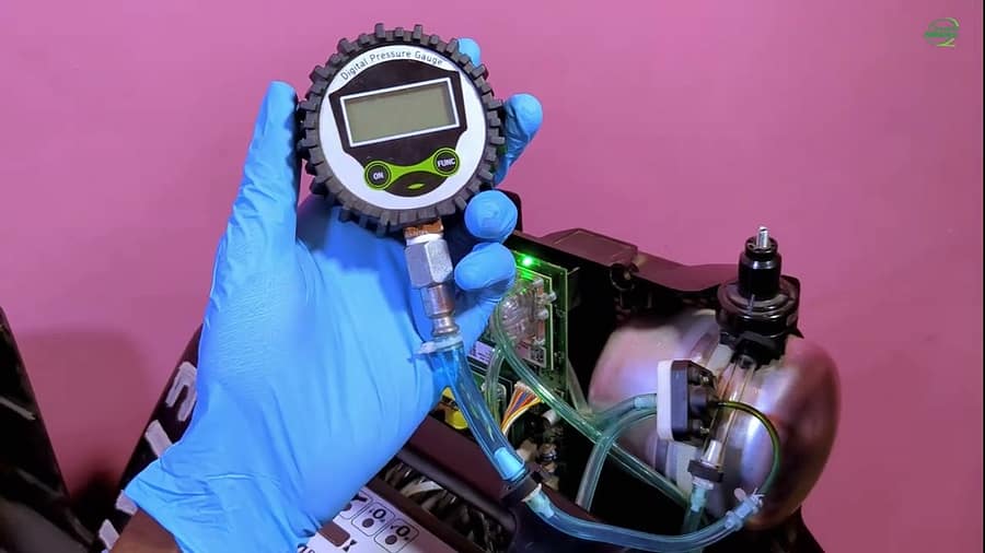
All functions are managed by a central printed circuit board (PCB). The PCB powers all major components, including the compressor, cooling fan, and the solenoid valves that control airflow. To monitor performance, the PCB receives data from two key sources: an ultrasonic oxygen sensor and a pressure sensor. This closed-loop system allows the machine to monitor its own output and trigger alarms when necessary.
Diagnostic Error Codes and Troubleshooting
The ability to interpret the M50’s self-diagnostics is fundamental to efficient service. The machine is programmed with a comprehensive set of alarm codes designed to direct a technician to the source of a fault.
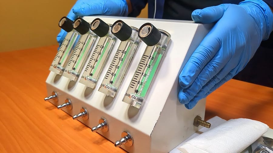
Safety Precautions As per industry best practice, always disconnect the device from the power source before removing covers for service. Be aware that oxygen concentrators create an oxygen-enriched environment; adhere to all fire safety protocols. Post-service performance verification must be conducted using a calibrated oxygen analyzer to ensure output purity meets manufacturer and clinical specifications.
Quick Reference Error Code Table
When an alarm sounds, the error code provides the most direct path to a diagnosis.
| Error Code | Fault Description | Potential Causes |
| H08 | Pressure-related issue. | A simple blockage in the pneumatic path or a low voltage supply hampering the compressor’s performance. |
| E01 | Fault with the temperature sensor on the main board. | A disconnected sensor or a faulty component on the PCB. |
| H02 | Internal temperature has exceeded 60 degrees Celsius. | Potential cooling fan failure or external/internal blockage of airflow. |
| Power Failure Alarm | Indicates a loss of mains power. | An issue with the facility’s power outlet or the unit’s fuse. |
Diagnostic Strategy
Fluency in the M50’s diagnostic language makes troubleshooting a more precise process. A generic “low oxygen” alarm, for instance, becomes a more defined starting point. The technician can immediately check the error code log to see if the machine is also reporting a pressure fault (H08), which would narrow the investigation significantly. This methodology allows a technician to quickly and accurately pinpoint the root cause of a failure.
Concluding Remarks and Video Guide
This level of diagnostic expertise not only accelerates repair time but also ensures that the service process is comprehensive and accurate, leading to more reliable outcomes.
To provide a complete visual tour of this machine, an in-depth video guide has been produced. The presentation covers all external and internal components, a full explanation of the diagnostic error codes, and a step-by-step disassembly procedure.
Watch the full teardown video here: