System Overview
For the biomedical technician, a thorough understanding of an oxygen concentrator’s electronics is critical for diagnosing faults that are not purely mechanical. In the J5 oxygen concentrator, the printed circuit board (PCB) acts as the central nervous system, distributing power and issuing commands to choreograph the entire oxygen generation process. This guide provides a detailed explanation of its electrical architecture.
Safety Precautions As per industry best practice, disconnect the device from the mains power source before removing covers for internal service. This guide discusses high-voltage circuits. Only qualified technicians should perform diagnostics on live electrical systems, using appropriate personal protective equipment (PPE) and following all electrical safety protocols.
Power Distribution Architecture
The electrical system is centered on the main control board, which manages power for the entire unit. The architecture can be understood as two distinct pathways.
High-Voltage AC Pathway
Power enters the unit through a main switch and is routed to the board’s primary connectors. From here, high-voltage AC power is sent directly to operate the system’s high-load components:
- The compressor
- The cooling fan
Low-Voltage Power Supply
A crucial part of the circuit is a step-down transformer, which takes the high-voltage AC input and reduces it to 15 volts AC. This low-voltage power is then supplied to the main control board, where it is converted into DC voltage to run the sensitive electronic components.
Control System and Logic
The Peak Microcontroller
The “brain” of the J5 concentrator is a Peak microcontroller located on the main control board. This chip executes the machine’s programming and is responsible for all control logic.
Microcontroller Functions
The microcontroller’s primary responsibilities include:
- Sending precisely timed signals to switch the four-way solenoid valve on and off.
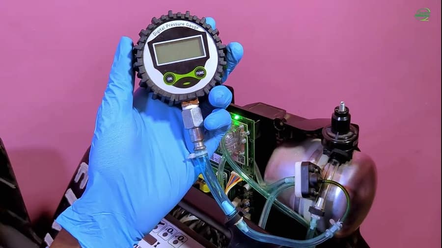
- Receiving and interpreting signals from the pressure sensor.
- Monitoring the system for faults.
- Controlling the indicator lights and buzzers to alert the user of any issues.
Electrical Troubleshooting Logic
Visualizing the electrical pathways provides a powerful layer of diagnostic capability. An understanding of the circuit allows a technician to troubleshoot with greater precision, especially for intermittent or electronic faults.
- Fault: Compressor fails to start.
- Troubleshooting Insight: Beyond the compressor itself, the fault could be an issue with the main board’s power-switching circuit.
- Fault: The four-way solenoid valve is not cycling.
- Troubleshooting Insight: The fault could lie with the signal from the microcontroller or with the low-voltage power supply originating from the transformer.
This knowledge enables diagnosis at a component level on the PCB, which can prevent the unnecessary cost of replacing the entire board and demonstrates a superior level of technical expertise.
Video Resource
To provide a clear and concise explanation of these electrical connections, a video guide is available that traces the flow of power throughout the J5 oxygen concentrator, detailing the role of the main board, transformer, and microcontroller.
Watch the full electrical system guide here: