Objective and Scope
The continuous production of purified oxygen in a concentrator, such as the NewLife Intensity 10, is dependent on the precise function of the four-way feed/waste solenoid valve. This component operates as a sophisticated pneumatic traffic director at the center of the pressure swing absorption cycle. This document details the valve’s architecture and operational sequence to provide biomedical professionals with a foundational understanding of this critical system.
Component Architecture
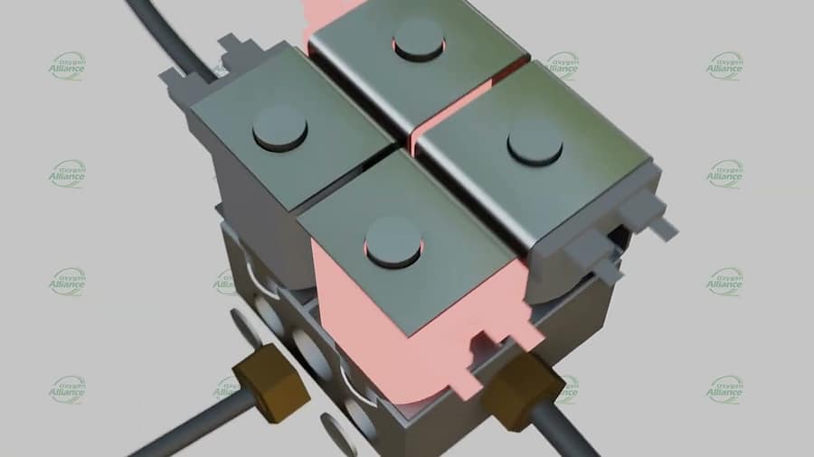
The AirSep valve is engineered with a specific configuration of ports and solenoids to manage the complex airflow required for oxygen generation.
Port Configuration
The valve body has four distinct ports:
- Inlet: Receives pressurized air from the compressor.
- Sieve Bed Outlets (x2): Two separate outlets that connect individually to each of the two sieve beds.
- Exhaust Port: Allows separated nitrogen gas to be vented from the system.
Solenoid Configuration
The valve’s action is controlled by four individual solenoids, which are small electromagnets. They are grouped by function:
- Feed Solenoids (x2): When energized, these open a path for pressurized air to enter one of the sieve beds.
- Waste/Exhaust Solenoids (x2): When energized, these open a path for nitrogen gas to exit the system from the opposite sieve bed.
Pressure Swing Absorption Cycle
The valve orchestrates a continuous, perfectly timed cycle by rapidly switching between two phases. This action allows the machine to produce an uninterrupted flow of purified oxygen.
Phase A: Pressurizing Sieve Bed 1 / Venting Sieve Bed 2
- The “feed” solenoid for Sieve Bed 1 and the “waste” solenoid for Sieve Bed 2 are simultaneously energized.
- The electromagnetic force pulls back the internal plungers of the energized solenoids.
- This action opens a pathway for compressed air to flow into the first sieve bed while simultaneously allowing nitrogen to be vented from the second.
Phase B: Pressurizing Sieve Bed 2 / Venting Sieve Bed 1
- After a set period, the first pair of solenoids is de-energized, and their internal springs push the plungers closed.
- Immediately, the opposite pair of solenoids—the “feed” solenoid for Sieve Bed 2 and the “waste” solenoid for Sieve Bed 1—is energized.
- This action directs compressed air into the second sieve bed while venting the first.
Diagnostic Implications
A deep understanding of this mechanical reality is invaluable for a service professional. When a machine fails to cycle correctly, the fault may lie within this valve assembly. A failure in even a single one of the four solenoids, or its controlling circuit, can bring the entire oxygen production process to a halt, which underscores the need for precise system diagnostics.
Video Resource
To help visualize this intricate process, a detailed 3D animation has been created to illustrate the complete operational cycle of the AirSep four-way solenoid valve, showing how the plungers move and how airflow is directed.
Watch the full animated guide here:

